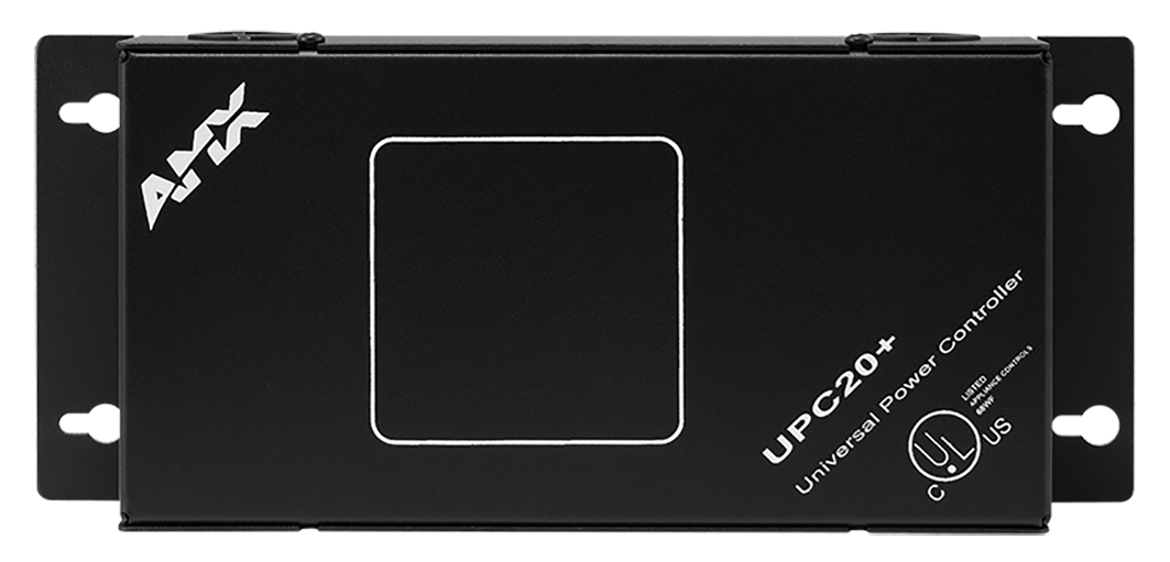

Designed for conduit installation, the Universal Power/Motor Controller, 20 A (110/220 VAC input) is a dual 20-amp AC power and motor controller. Configure a wide range of power and motor control modes for a full range of devices ranging from simple wall panels with low voltage contact closure to large systems requiring high voltage contact closure.
The UPC20+ supports two primary operating modes. In Motor Control Mode, the two relays are automatically activated in sequence with an adjustable delay from 0 to 90 seconds. In this mode, there are three control options:
< >Single Button Mode operates with one pushbutton in a sequence: Up, Stop, Down, Stop and so on for each successive button press.Two/Three Button Mode operates with two pushbuttons, one for Up and one for Down and optionally one for stop.Momentary On/Off operates the first relay only while the button is pressed and then second the relay activates when the button is released.Momentary Power Mode operates the selected relay only while the button is pressed. The relay is de-activated when the button is released.Latching Power Mode toggles between activating and deactivating the selected relay on each successive button press.Two Button On/Off Mode uses two buttons for each relay, one to activate and one to deactivate.1, 2 and 3-button logic modesLocal test switches with status LEDs120, 240, and 277 VAC control capabilityETL listed.
SPECIFICATIONS
DIMENSIONS (HWD)
- 8 1/2" (10 1/2" (including flange) x 4 1/2" x 2 3/16" (22 cm (27 cm (including flange) x 11 cm x 6 cm)
- RU: 5
WEIGHT
3 lbs (1.4 kg)
POWER
- Self-powered when used with 110/220 VAC applications
- Power input options (for control board):
- 120/240V ~, 50-60 Hz, 0.05/0.025A
- 12 VDC, 0.2A max - Power output per relay
- 20A @ 120/240V ~, 50-60 Hz (RESISTIVE LOAD)
- 6A @ 277V ~, 50-60 Hz (FLUORESCENT BALLAST)
- 1 HP @ 120V ~, 50-60 Hz (INDUCTIVE LOAD)
- 2 HP @ 240V ~, 50-60 Hz (INDUCTIVE LOAD)
Total Current through both relays CANNOT exceed 20 amp.
ENCLOSURE
Metal with black matte finish, knockouts for conduit
INPUTS
- 4 closure inputs, operation defined by mode
- One IR remote sensor input
- Motor Control mode alternates between the timed operation of the two power relays
- Power Control mode allows independent control of both power relays
INPUT POWER SWITCH (S1)
- Set this switch according to the high voltage wiring that will be connected to terminals 5 and 6 on P1.
- Set switch S1 to the line input voltage value used before applying power to the UPC20+
HIGH VOLTAGE TERMINAL BLOCK (P1)
High voltage input and output wiring for motor or power control.
LOW VOLTAGE AND CONTROL TERMINAL BLOCK (P2)
Contact closure, open-collector or CMOS logic level remote control wiring Inputs 5 - 8 are referenced to the common connection at pin 4
JUMPER JP1
Sets control mode of the unit to contact closure or remote sensor serial data
TEST SWITCHES (PB1 AND PB2)
Provides local operation of relays K1 and K2 for testing power circuits or motors connected to the relay terminals. An LED indicates relay power applied
MOTOR TIME DELAY POTENTIOMETER (R8)
Only used in motor control modes. User adjusted for setting relay release time between 0 and 90 seconds
DIP SWITCH (S2)
Provides selection of control mode options
CONTROL INPUTS
- 4 closure inputs; operation defined by mode
- Motor control mode alternates between the timed operation of the two power relays
- Power control mode allows independent control of both power relays
CONTROL PORTS
(2) 2400 W power relays. Total combined current through both relays is 20 Amps
CERTIFICATIONS
UL, C-UL, CE
ENVIRONMENTAL
Operating/Storage Temperature: 55º C